Your boat's electrical system quietly does more work than most other systems aboard combined. It starts the engine, powers navigation electronics, keeps food cold, runs the bilge pump, and provides lighting and shore power AC throughout the vessel. When it works correctly, you never think about it. When it fails, the consequences range from a dead battery to an electrical fire to electrocution. The good news is that a handful of targeted upgrades address the most common and most dangerous failure points. None of these require an ABYC-certified electrician for the straightforward installations, and every one of them pays dividends in safety and reliability.
- To protect against electric shock drowning: Install GFCIs and ELCIs
- To prevent wiring fires: Fix Faulty Wiring Before It Becomes a Fire Hazard
- For shore power safety: Replace Worn Shore Power Cords and Connectors
- For growing electrical loads: Upgrade Your Breaker Panel
- For overloaded battery terminals: Stop Stacking Connections on Battery Terminals
- FAQ: Electrical Upgrades for a Safer Boat
- Related Articles
Install GFCIs and ELCIs to Prevent Electric Shock Drowning
Electric shock drowning (ESD) is one of the most misunderstood hazards in recreational boating. It occurs when AC current leaks from a boat or dock into surrounding water, creating a voltage gradient. A swimmer who enters that field feels an increasing level of electrical current as they move from a low-voltage area toward a higher-voltage area. At low levels this causes muscle paralysis that prevents the swimmer from reaching safety; at higher levels it is fatal. The swimmer appears to drown, but the cause is electrocution.
ESD is primarily a freshwater hazard. Saltwater’s higher conductivity disperses leaking current rapidly, reducing the concentration needed to harm a swimmer. In fresh water, current concentrates. A dock full of boats plugged into shore power in an inland marina or lake creates a potentially serious ESD environment, and neither the victim nor bystanders necessarily know what is happening.
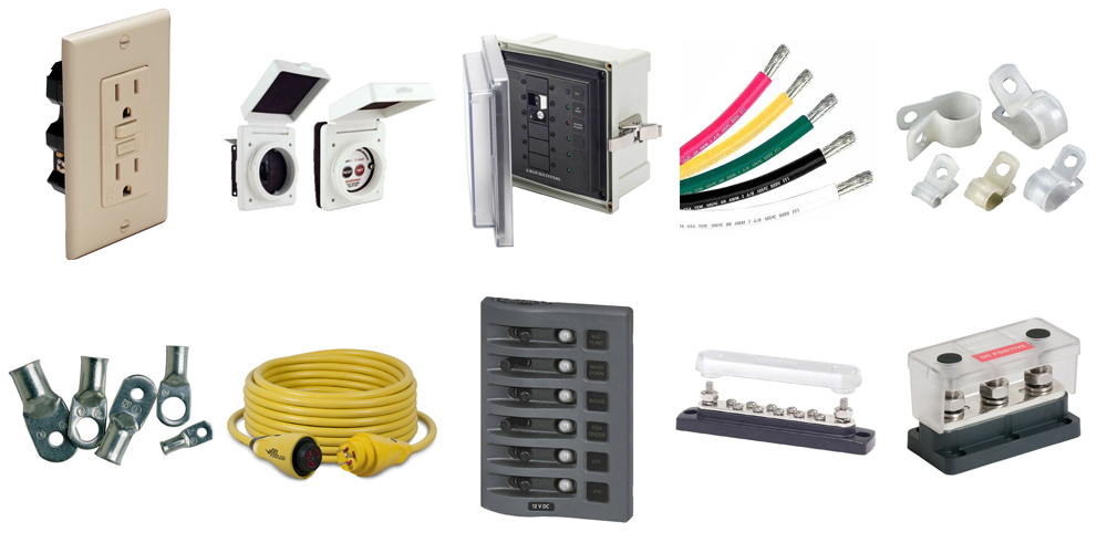
The source of the hazard is almost always an ungrounded AC circuit or stray current leaking from shore power. Two device categories address this:
GFCI Outlet (upper left), ELCI Sensing Module and Breaker Housing (upper right), Enclosed ELCI Main Circuit Breaker Panel (bottom center).
GFCI: Ground Fault Circuit Interrupters
A GFCI monitors current flow in the hot and neutral wires of an AC circuit. Under normal conditions, those currents are equal. When current leaks to ground through a fault, the imbalance is detected and the circuit trips within milliseconds. GFCIs are required to trip at 5 milliamps (5/1000 of an amp) — fast enough to prevent a lethal shock in most circumstances.
Per ABYC Standard E-11, GFCI-protected outlets are required in the head, galley, engine room, and weather deck of any boat with AC electrical systems. If your boat has standard outlets in any of these locations, replacement with GFCI outlets is one of the highest-value safety upgrades you can make. The installation is straightforward: the GFCI outlet wires in identically to a standard outlet and includes its own test/reset buttons. One GFCI can also protect downstream outlets on the same circuit using the LINE and LOAD terminals.
ELCI: Equipment Leakage Circuit Interrupters
Where a GFCI protects a branch circuit, an ELCI protects the entire boat. ABYC E-11.11.1 requires an ELCI to be installed at or in addition to the main shore power disconnect circuit breaker. The ELCI monitors total current leakage from the vessel and trips at 30 milliamps — higher than a GFCI’s 5mA threshold to avoid nuisance trips from the aggregate minor leakage that a loaded boat’s wiring inevitably produces, but still fast enough to interrupt current before it reaches dangerous levels in the water.
An ELCI trips at the source, cutting all shore power to the boat before current can build to lethal concentrations in the surrounding water. This is what makes it the most important single upgrade for any boat that plugs into fresh or brackish water shore power.
Note: An isolation transformer, when installed within 10 feet of the shore power inlet, provides an alternative to an ELCI under some versions of the ABYC standard. An isolation transformer separates the boat’s AC system from shore power entirely, eliminating the path by which shore power current can reach the water. It also eliminates galvanic corrosion from stray DC current traveling through the shore power ground. Isolation transformers are more expensive than ELCIs but provide broader protection benefits for boats that spend significant time at dock on shore power.
Practical Installation Notes
- Test your GFCI outlets monthly using the test button. A GFCI that does not trip on test has failed and must be replaced.
- Test your ELCI the same way. The test button on an ELCI-equipped panel should trip the main breaker.
- Never swim near boats that are connected to shore power, even if all the boats appear in good condition. Faults on a neighboring vessel can put current in the water around yours.
- Install a dock power indicator light or shore power monitor to verify polarity and voltage at the outlet before connecting. Reverse polarity at a marina outlet is more common than most boaters realize and bypasses ground fault protection.
Fix Faulty Wiring Before It Becomes a Fire Hazard
The NFPA and BoatUS Foundation consistently identify faulty wiring as the leading cause of fires aboard recreational boats. Unlike a car, which is relatively stable and dry, a boat is constantly flexing, vibrating, exposed to salt air and moisture, and subject to temperature swings that accelerate insulation degradation. Wiring that was adequate when the boat was built may be dangerous fifteen years later — and wiring installed by a previous owner using automotive wire or undersized conductors may be dangerous now.
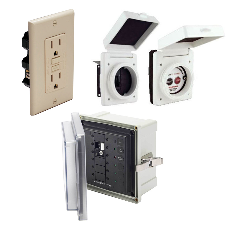
West Marine offers a full selection of marine wire and wire terminals.
Why Marine-Grade Wire Matters
Automotive wire uses bare copper conductors in a dry environment. Marine wire uses stranded, tinned copper in a wet, corrosive environment. The difference matters in two specific ways. First, bare copper corrodes from the outside in when exposed to salt air and moisture, increasing resistance and generating heat at connections. Tinned copper resists this corrosion at the strand level. Second, stranded conductors flex without work-hardening and breaking the way solid conductors do under vibration. Using automotive wire on a boat is a false economy that typically manifests as a wiring fire years later.
ABYC E-11 specifies minimum wire sizes for DC and AC circuits based on current load and circuit length. Undersized wire is the most common wiring deficiency found in boat surveys — it may carry the load adequately at first, but resistance heating accelerates insulation degradation over time. If you are unsure whether your boat’s existing wiring meets ABYC ampacity standards, our West Advisor article Marine Wire Size and Ampacity provides complete sizing tables.
Connections: The Most Common Failure Point
Most wiring fires on boats start not at the wire itself but at a connection. A high-resistance connection generates heat; heat degrades insulation; degraded insulation can ignite adjacent materials. The three most common connection problems are:
- Twisted and taped connections: The automotive practice of twisting wires together and wrapping with electrical tape has no place on a boat. Twist connections loosen over time from vibration, increasing resistance. Use marine-grade crimp connectors instead. Heat-shrink crimp terminals (tinned, with a sealant-lined heat-shrink sleeve) are the preferred choice for any environment where moisture is present.
- Corroded terminals: Green or white oxidation on wire terminals indicates corrosion. A corroded terminal may appear connected but has dramatically increased resistance. Replace corroded terminals entirely rather than attempting to clean them — corrosion penetrates the strands of the wire and cleaning the visible surface does not restore the conductor.
- Unsupported wire runs: Wire that hangs free and rubs against structure or other wires will eventually chafe through its insulation. ABYC requires wire to be supported at regular intervals and protected from chafe at any point where it passes through a bulkhead or near a moving component.
What to Look for During a Wiring Inspection
- Brittle, cracked, or discolored insulation anywhere along a wire run
- Green or white corrosion at any terminal or connection
- Heat discoloration (brown or black) at connections or near circuit breakers
- Wire runs that are not secured and can abrade against structure
- Wires passing through bulkheads without chafe protection
- Any evidence of previous overheating: melted insulation, burn marks, or the smell of burnt plastic in a locker or behind a panel
Inspect wiring at least once per season. Any of the above signs warrant immediate attention — not at the end of the season, but before the next trip.
Replace Worn Shore Power Cords and Connectors
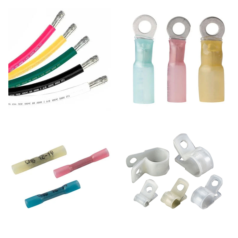
Shore power cords carry 30 or 50 amps of AC current into the boat through a weather-exposed connection that gets plugged and unplugged repeatedly, coiled and stored, stepped on, and subjected to saltwater spray. They fail in ways that are both obvious (a melted plug is hard to miss) and subtle (internal connection degradation that builds heat invisibly over months).
Marine shore power cord sets by Marinco and SmartPlug. Left: Traditional shore power cords by Marinco with easy-lock threaded ring. Top right: EEL (Easily Engaged Lock) ShorePower™ Cordset by Marinco with jaw-clamp feature for easy one-handed operation. Bottom right: SmartPlug shore power cord with locking inlet cover and TPE Dyna-flex cord seal for a weatherproof connection.
Inspection Protocol
Before connecting to shore power, inspect both the cord and the inlet on the boat. Replace the cord immediately if you find any of the following:
- Discoloration, melting, or heat distortion at the plug or connector body
- Cracks in the cord jacket, particularly near the plug where flexing is greatest
- Corrosion or pitting on the blade contacts inside the plug
- A plug that no longer locks firmly into the inlet (the locking ring spins freely or the connection feels loose)
- Any burning smell when the cord is plugged in and energized
Also inspect the inlet on the boat itself. A scored or discolored inlet receptacle indicates the cord has been overheating at that connection point. Replacing the cord alone without replacing a damaged inlet will produce the same problem on the new cord.
Upgrade Options
Standard Marinco shore power cords with the threaded locking ring are widely available and reliable when maintained. Two upgrade options address the most common failure modes:
Marinco EEL (Easily Engaged Lock) Shore Power Cords replace the threaded ring with a jaw-clamp mechanism that locks with one hand. The advantage is that one-handed connection means the plug seats fully and locks reliably every time, eliminating the partial engagement that causes intermittent contact and heat buildup at the inlet. On a dark dock in the rain with a boat moving on its lines, this is a meaningful practical improvement.
SmartPlug shore power systems redesign the plug-and-inlet geometry to provide a larger contact surface and a weatherproof seal between plug and inlet. The TPE Dyna-flex cord is more flexible than standard jacketing and less prone to cracking at the plug end. The locking system uses a simple lever rather than a threaded ring. SmartPlug is a complete system — the plug and the boat-side inlet must both be SmartPlug; they are not interchangeable with standard Marinco inlets.
Upgrade Your Breaker Panel
Most production boats are delivered with a panel that has exactly enough circuit positions for the equipment installed at the factory — which means no room for additions. As owners add electronics, refrigeration, additional lighting, inverters, and other equipment, the typical response is to share circuits, add multiple devices to a single breaker, or run new wiring without overcurrent protection. All of these create real hazards.
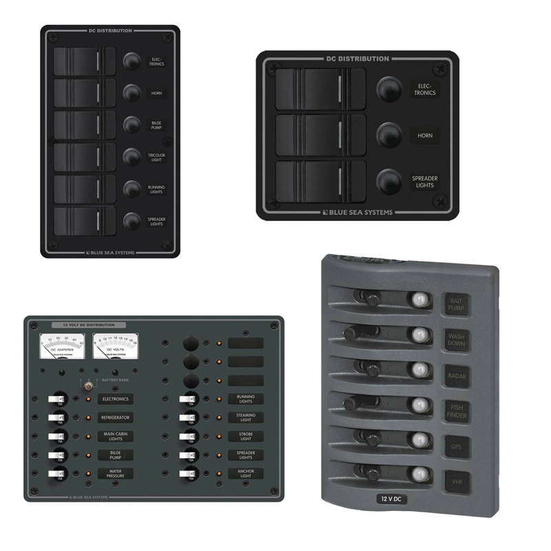
Examples of fuse and breaker distribution panels by Blue Sea Systems.
Understanding Overcurrent Protection
Every circuit on a boat must have overcurrent protection (a fuse or circuit breaker) sized to protect the wire, not the device. This is a critical distinction: the breaker protects the wiring from overheating, not the equipment from damage. A 20-amp breaker on a circuit wired with 12-gauge wire is correct sizing for the wire. Running two 15-amp appliances on that circuit is a problem even if the breaker does not trip immediately — the sustained current will heat the wire.
When evaluating whether your current panel is adequate:
- Calculate the total continuous current draw of all devices that might run simultaneously on each circuit
- Confirm the breaker for each circuit is sized appropriately for the wire gauge (ABYC tables in our Marine Wire Size and Ampacity article)
- Count available unused circuit positions — if you have none, any new equipment requires either a new panel or a sub-panel
- Check whether your main DC bus and battery connections are sized for the total system load, not just individual circuits
When to Upgrade
A panel upgrade makes sense when your panel has no available circuit positions, when existing breakers are running consistently warm (indicating near-continuous high loading), when you are adding high-draw equipment such as refrigeration, air conditioning, a bow thruster, or a significant electronics upgrade, or when the existing panel is a blade-fuse type that does not allow quick circuit identification and reset. Blue Sea Systems and Paneltronics produce ABYC-compliant panels in a wide range of circuit counts and configurations. Switching from a fuse panel to a circuit breaker panel eliminates the ongoing cost and inconvenience of replacing blown fuses and makes tripped circuits immediately visible and resettable.
Stop Stacking Connections on Battery Terminals
Open the battery compartment on a boat that has been progressively upgraded over several years, and you will often find a battery terminal with four, five, or six ring terminals stacked under a single nut. This is a genuinely dangerous configuration. The physical connection between the bottom ring terminal and the battery post is solid, but the connection between successive stacked terminals depends entirely on contact pressure from the nut. As the stack grows, the nut torque distributes less evenly through the pile, the bottom terminals loosen slightly, and contact resistance increases. High resistance at a heavily loaded terminal generates significant heat. Heat accelerates corrosion. Corroded connections generate more heat. The failure mode, when it arrives, is typically an electrical fire at the battery.
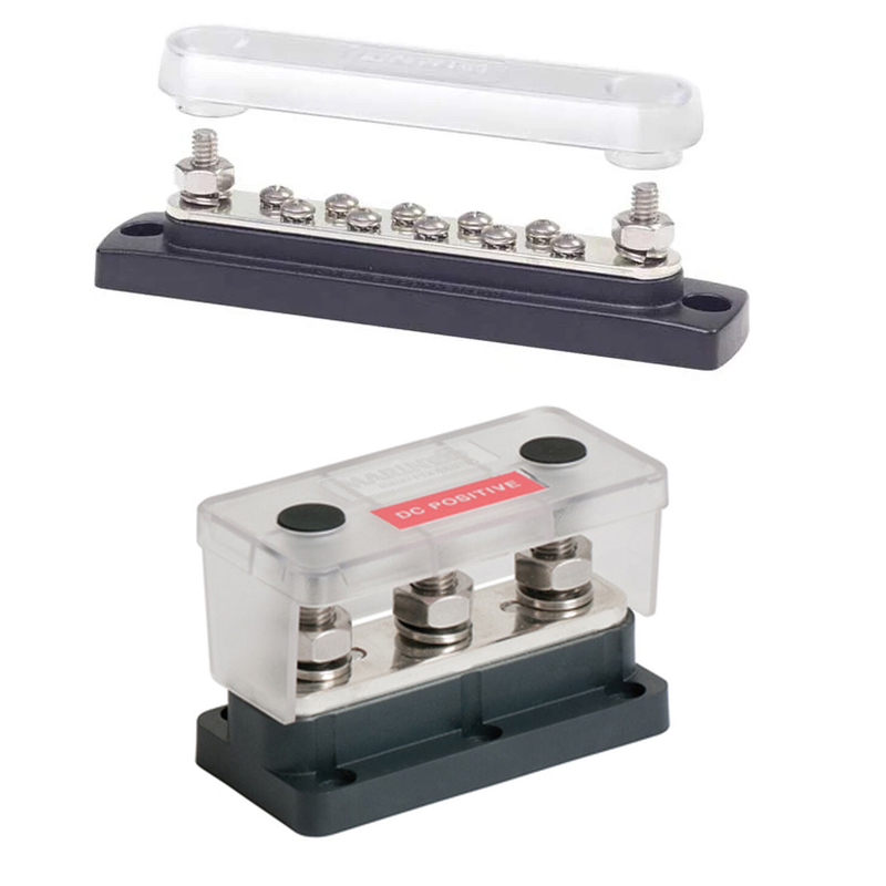
Examples of busbars by Blue Sea Systems.
The Bus Bar Solution
A bus bar (also spelled busbar) is a copper or tin-plated copper bar with multiple terminal positions. A single large-gauge cable connects the battery to the bus bar, and each circuit connects to the bus bar at its own dedicated terminal position with its own fastener. Every connection is solid and independent. The battery terminal carries only one connection. The bus bar can be inspected and individual connections tightened or replaced without disturbing others.
Separate positive and negative bus bars are the correct configuration. The positive bus bar typically sits downstream of the main battery switch and the main fuse or circuit breaker. The negative bus bar provides the return path for all circuits. Both should be mounted in a dry, accessible location with covers protecting the terminals from accidental short circuits.
ABYC Rules for Battery Connections
- ABYC E-11 limits the number of connections on a battery terminal to one — one cable to the battery switch or to the bus bar. Additional circuits must connect at the bus bar, not the battery.
- The cable between the battery and the bus bar must be sized for the total current draw of all circuits, not just the largest circuit.
- Overcurrent protection (fuse or circuit breaker) must be installed as close to the battery positive terminal as practical — ABYC specifies within 7 inches for most installations, or within 40 inches if the wiring is protected throughout its length. This protects the wire from battery to overcurrent device, which is the most dangerous unprotected conductor on most boats.
A Safer Boat Starts with Smart Upgrades
Your boat’s electrical system is its nervous system. Keep it in top shape, and you’ll avoid the headaches and dangers of electrical failures. These five upgrades address the leading causes of boat electrical fires and electrocution hazards, and each one builds on the others — proper wiring feeds a proper panel, which distributes through proper bus bars, all protected upstream by GFCIs and ELCIs and fed through a sound shore power connection. Done right, the entire system becomes reliable enough that you genuinely never have to think about it.
For complex electrical work or any time you are uncertain about compliance with ABYC standards, consult an ABYC-certified marine electrician. The ABYC certification is specific to marine electrical systems and represents a meaningful level of expertise beyond a general electrician’s license.
We’re Here to Help
At West Marine, we carry the full range of products needed for any of these upgrades, from GFCI outlets and ELCI panels to marine wire, shore power cords, breaker panels, and bus bars. Our crew includes knowledgeable boaters who have done many of these installations themselves. Find your nearest West Marine store for hands-on help selecting the right components for your boat.
FAQ: Electrical Upgrades for a Safer Boat
What is the difference between a GFCI and an ELCI?
A GFCI (Ground Fault Circuit Interrupter) protects a single branch circuit and trips at 5 milliamps of current leakage. It is installed at the outlet level and protects people from shock at that outlet. An ELCI (Equipment Leakage Circuit Interrupter) protects the entire boat’s AC system and is installed at the main shore power disconnect. It trips at 30 milliamps — a higher threshold to avoid nuisance trips from aggregate minor leakage across all circuits, but still fast enough to prevent dangerous current from building in the surrounding water. Both are required by ABYC E-11 for boats with AC electrical systems. GFCIs protect the person using a specific outlet; the ELCI protects swimmers in the water around the boat.
What is Electric Shock Drowning (ESD) and how can I prevent it?
ESD occurs when AC current leaks from a boat or dock into surrounding water, creating a voltage gradient. A swimmer who enters the field can experience muscle paralysis and drown. ESD is primarily a freshwater hazard because saltwater’s conductivity disperses current rather than concentrating it. Prevention: install an ELCI at the main shore power disconnect; install GFCI outlets in all required locations; inspect shore power cords before every connection; and never swim near boats or docks with active shore power connections.
How often should I inspect my boat’s wiring?
At minimum, once per season as part of your annual commissioning. Also inspect after any significant impact (grounding, collision, hard landing), after any water intrusion event that reached the electrical system, and any time you notice a circuit behaving unexpectedly (breaker tripping repeatedly, device running hot, burning smell from any compartment). Look specifically for cracked or brittle insulation, corrosion at terminals, unsupported wire runs, and any evidence of past overheating.
What are the signs that my shore power cord needs to be replaced?
Replace immediately if you find discoloration, melting, or heat distortion at the plug; cracks in the cord jacket near the plug; corrosion or pitting on the blade contacts; a locking ring that no longer holds the plug firmly; or any burning smell when the cord is energized. Also inspect the boat-side inlet — a scored or discolored inlet means the connection has been overheating, and the inlet must be replaced alongside the cord or the problem will recur on the new cord.
Why is the overcurrent protection sized to the wire rather than the device?
The circuit breaker or fuse protects the wire from overheating, not the device from damage. If a breaker is sized for the device rather than the wire, a fault that draws more current than the wire can safely carry may not trip the breaker before the wire has already overheated. The correct sequence is: determine the maximum safe current for the wire gauge at that circuit length (using ABYC ampacity tables), then select a breaker rated at or below that ampacity. Device protection (if needed) is handled separately at the device level.
What are the ABYC rules for battery connections?
ABYC E-11 limits each battery terminal to a single connection: one cable running to a bus bar or battery switch. All other circuits must connect at the bus bar, not the battery. The cable from battery to bus bar must be sized for total system load. Overcurrent protection must be installed as close to the battery positive terminal as practical — within 7 inches for most installations, or within 40 inches if the wiring is protected throughout. This protects the highest-risk conductor on the boat: the unprotected run between battery and first fuse or breaker.
Related Articles
- Marine Wire Size and Ampacity
- Do-It-Yourself: Shore Power
- Standards and Practices of DC Marine Wiring
- Marine Grounding Systems
- ELCI/GFCI Electrical Shock Protection
- Top 3 Marine Circuit Breakers for Safer Electrical Systems in 2025
- Ten Deadly Conditions of Boat Electrical Systems
- Circuit Protection and Power Distribution